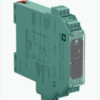
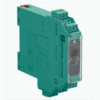
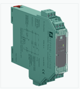
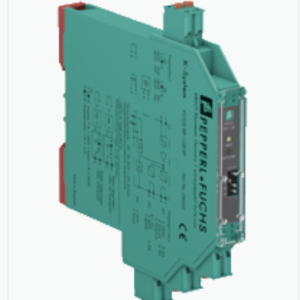
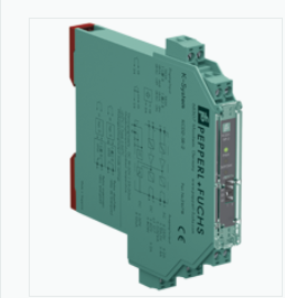
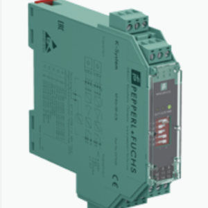
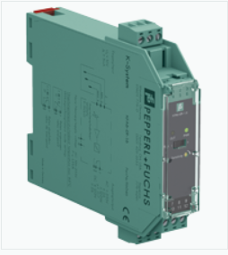
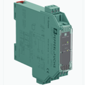
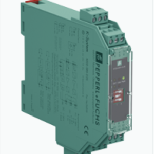
RELAY MODULE KFD2-RSH-1.2E.L2 – PEPPERL FUCHS VIỆT NAM
Hãng: PEPPERL – FUCHS
Tên sản phẩm: RELAY MODULE KFD2-RSH-1.2E.L2 – PEPPERL FUCHS VIỆT NAM
Bảo Hành : 12 Tháng ( chỉ bảo hành lỗi do nhà sản xuất )
Tình trạng hàng hóa mới 100%
Danh mục: K-System, PEPPERL+FUCHS, Relay Module
Từ khóa: đại lý phân phối KFD2-RSH-1.2E.L2, đại lý phân phối pepperl fuchs, đại lý phân phối pepperl fuchs bắc giang, đại lý phân phối pepperl fuchs bắc ninh, đại lý phân phối pepperl fuchs bình dương, đại lý phân phối pepperl fuchs cần thơ, đại lý phân phối pepperl fuchs đà nẵng, đại lý phân phối pepperl fuchs đồng nai, đại lý phân phối pepperl fuchs hà nội, đại lý phân phối pepperl fuchs hải phòng, đại lý phân phối pepperl fuchs hồ chí minh, đại lý phân phối pepperl fuchs KFD2-RSH-1.2E.L2, đại lý phân phối pepperl fuchs long an, đại lý phân phối pepperl fuchs quảng nam, đại lý phân phối pepperl fuchs thái nguyên, đại lý phân phối relay module, đại lý phân phối relay module bình dương, đại lý phân phối relay module cần thơ, đại lý phân phối relay module đà nẵng, đại lý phân phối relay module đồng nai, đại lý phân phối relay module hà nội, đại lý phân phối relay module hồ chí minh, đại lý phân phối relay module KFD2-RSH-1.2E.L2, đại lý phân phối relay module KFD2-RSH-1.2E.L2 bắc giang, đại lý phân phối relay module KFD2-RSH-1.2E.L2 bắc ninh, đại lý phân phối relay module KFD2-RSH-1.2E.L2 bình dương, đại lý phân phối relay module KFD2-RSH-1.2E.L2 bình định, đại lý phân phối relay module KFD2-RSH-1.2E.L2 cần thơ, đại lý phân phối relay module KFD2-RSH-1.2E.L2 đà nẵng, đại lý phân phối relay module KFD2-RSH-1.2E.L2 đồng nai, đại lý phân phối relay module KFD2-RSH-1.2E.L2 hà nội, đại lý phân phối relay module KFD2-RSH-1.2E.L2 hà tĩnh, đại lý phân phối relay module KFD2-RSH-1.2E.L2 hải phòng, đại lý phân phối relay module KFD2-RSH-1.2E.L2 hồ chí minh, đại lý phân phối relay module KFD2-RSH-1.2E.L2 khánh hoà, đại lý phân phối relay module KFD2-RSH-1.2E.L2 kiên giang, đại lý phân phối relay module KFD2-RSH-1.2E.L2 long an, đại lý phân phối relay module KFD2-RSH-1.2E.L2 nghệ an, đại lý phân phối relay module KFD2-RSH-1.2E.L2 quảng nam, đại lý phân phối relay module KFD2-RSH-1.2E.L2 tây ninh, đại lý phân phối relay module KFD2-RSH-1.2E.L2 thái nguyên, đại lý phân phối relay module KFD2-RSH-1.2E.L2 thanh hóa, đại lý phân phối relay module KFD2-RSH-1.2E.L2 vũng tàu, đại lý phân phối relay module pepperl fuchs, đại lý phân phối relay module tây ninh, KFD2-RSH-1.2E.L2, KFD2-RSH-1.2E.L2 pepperl fuchs, KFD2-RSH-1.2E.L2 relay module, pepperl fuchs KFD2-RSH-1.2E.L2, relay module KFD2-RSH-1.2E.L2
RELAY MODULE KFD2-RSH-1.2E.L2
TÍNH NĂNG NỔI BẬT
Bộ điều hòa tín hiệu này cung cấp sự cách ly điện giữa các mạch trường và mạch điều khiển.
Thiết bị là một mô-đun rơle thích hợp cho các ứng dụng chuyển mạch tải một cách an toàn. Thiết bị cô lập các mạch tải lên đến 60 V DC và mạch điều khiển 24 V DC.
Chức năng được cung cấp năng lượng đến mức an toàn (ETS) được phép cho các ứng dụng SIL 3.
Lỗi nội bộ hoặc lỗi đường dây được báo hiệu bằng sự thay đổi trở kháng của đầu vào tiếp điểm rơle và đầu ra tiếp điểm rơle bổ sung.
Lỗi được báo hiệu bằng đèn LED và đầu ra thông báo lỗi tập thể riêng biệt.
- Bộ điều hòa tín hiệu 1 kênh.
- Nguồn cung cấp 24 V DC.
- Đầu vào logic 19 V DC … 26.4 V DC.
- Điện áp có thể kết nối được khuyến nghị 8 V DC … 60 V DC.
- Ngõ ra tiếp điểm rơ le cho chức năng an toàn được cung cấp năng lượng
- Độ trong suốt của lỗi đường dây (LFT)
- Chức năng chẩn đoán
- Tối đa 3 acc SIL. theo IEC / EN 61508.
THÔNG SỐ KỸ THUẬT
| General specifications | ||
|---|---|---|
| Signal type | Digital Output | |
| Functional safety related parameters | ||
| Safety Integrity Level (SIL) | SIL 3 | |
| Systematic capability (SC) | SC 3 | |
| Supply | ||
| Connection | Power Rail or terminals 14+, 15- | |
| Rated voltage | 19 … 26.4 V DC | |
| Input current | max. 35 mA at 24 V DC , max. 44 mA at 19 V DC , with enabled internal fault detection | |
| Power consumption | < 1.7 W , includes the power consumption of the digital input , see derating curves | |
| Input | ||
| Connection side | control side | |
| Connection | terminals 7+, 8- | |
| Pulse/Pause ratio | min. 150 ms / min. 150 ms with disabled internal fault detection min. 1 s / min. 1 s with enabled internal fault detection |
|
| Test pulse length | max. 2 ms from DO card | |
| Signal level | 0-signal: -5 … 5 V DC 1-signal: 19 … 26.4 V DC |
|
| Rated current | 0-signal: typ. 1.6 mA at 1.5 V DC; typ. 8 mA at 3 V DC (maximum leakage current DO card) 1-signal: ≥ 36 mA (minimum load current DO card) |
|
| Inrush current | < 200 mA after 100 µs | |
| Output | ||
| Connection side | field side | |
| Connection | external voltage : terminals 5+, 2- load : terminals 6, 3 |
|
| Connectable voltage | 8 … 60 V DC | |
| Power dissipation | < 3.3 W at 5 A , see derating curves | |
| Contact loading | 30 V DC / 5 A resistive load , see derating curves | |
| Minimum switch current | 10 mA | |
| Mechanical life | 5 x 10⁶ switching cycles | |
| Line fault detection | low voltage < 5 V DC undercurrent: 10 mA DC; overcurrent: 2.2 A DC (relay energized) breakage: 8.2 kΩ; short-circuit: 11 Ω (load, relay de-energized) |
|
| Fault indication output | ||
| Connection | terminals 10, 11 | |
| Contact loading | 30 V DC/ 0.5 A resistive load | |
| Reaction time | < 2 s | |
| Mechanical life | 105 switching cycles | |
| Transfer characteristics | ||
| Switching frequency | < 3 Hz with disabled internal fault detection < 0.5 Hz with enabled internal fault detection |
|
| Galvanic isolation | ||
| Input/power supply | basic insulation according to IEC/EN 61010-1, rated insulation voltage 60 Veff | |
| Input/fault indication output | basic insulation according to IEC/EN 61010-1, rated insulation voltage 30 Veff | |
| Output/other circuits | reinforced insulation according to IEC/EN 61010-1, rated insulation voltage 300 Veff | |
| Indicators/settings | ||
| Display elements | LEDs | |
| Control elements | DIP switch | |
| Configuration | via DIP switches | |
| Labeling | space for labeling at the front | |
| Directive conformity | ||
| Electromagnetic compatibility | ||
| Directive 2014/30/EU | EN 61326-1:2013 (industrial locations) | |
| Conformity | ||
| Electromagnetic compatibility | NE 21:2017 , IEC/EN 61326-3-2:2018 , EN 61326-3-1:2017 | |
| Degree of protection | IEC 60529:2013 | |
| Protection against electrical shock | EN 61010-1:2010 | |
| Ambient conditions | ||
| Ambient temperature | -20 … 60 °C (-4 … 140 °F) Observe the temperature range limited by derating, see section derating. |
|
| Mechanical specifications | ||
| Degree of protection | IP20 | |
| Connection | screw terminals | |
| Mass | approx. 134 g | |
| Dimensions | 20 x 119 x 115 mm (0.8 x 4.7 x 4.5 inch) (W x H x D) , housing type B2 | |
| Mounting | on 35 mm DIN mounting rail acc. to EN 60715:2001 | |
| Data for application in connection with hazardous areas | ||
| Certificate | PF 17 CERT 4305 X | |
| Marking |  II 3G Ex nC ec IIC T4 Gc [device in zone 2] II 3G Ex nC ec IIC T4 Gc [device in zone 2] |
|
| Directive conformity | ||
| Directive 2014/34/EU | EN 60079-0:2012+A11:2013 , EN 60079-7:2015 , EN 60079-15:2010 | |
| International approvals | ||
| UL approval | E106378 | |
Sản phẩm tương tự
Được xếp hạng 2.43 5 sao
Được xếp hạng 2.42 5 sao
Được xếp hạng 2.45 5 sao
Được xếp hạng 2.42 5 sao
Được xếp hạng 2.39 5 sao
Được xếp hạng 2.57 5 sao
Được xếp hạng 2.37 5 sao
