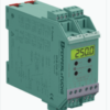
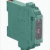
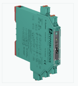
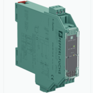
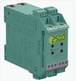
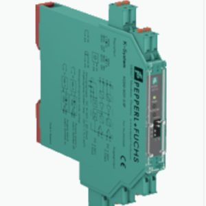
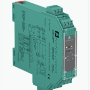
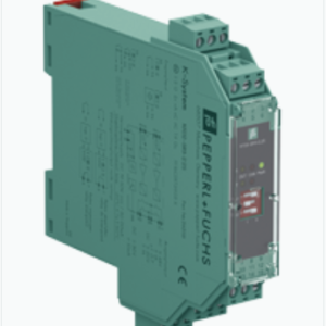
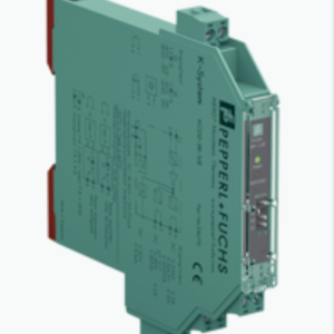
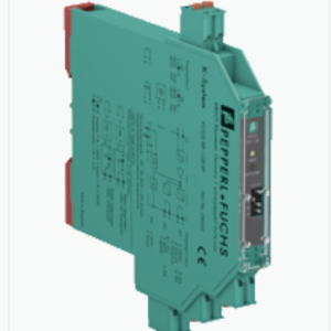
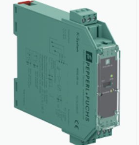
BỘ KHUẾCH ĐẠI TÍN HIỆU SWITCH AMPLIFIER KCD2-SR-2.SP – PEPPERL FUCHS VIỆT NAM
Hãng: PEPPERL – FUCHS
Tên sản phẩm: BỘ KHUẾCH ĐẠI TÍN HIỆU SWITCH AMPLIFIER KCD2-SR-2.SP – PEPPERL FUCHS VIỆT NAM
Bảo Hành : 12 Tháng ( chỉ bảo hành lỗi do nhà sản xuất )
Tình trạng hàng hóa mới 100%
Danh mục: K-System, PEPPERL+FUCHS, Switch Amplifiers
Từ khóa: Bộ khuếch đại tín hiệu, bộ khuếch đại tín hiệu bắc giang, bộ khuếch đại tín hiệu bắc ninh, bộ khuếch đại tín hiệu bình dương, bộ khuếch đại tín hiệu bình định, bộ khuếch đại tín hiệu bình thuận, bộ khuếch đại tín hiệu cần thơ, bộ khuếch đại tín hiệu đà nẵng, bộ khuếch đại tín hiệu đồng nai, bộ khuếch đại tín hiệu hà nội, bộ khuếch đại tín hiệu hà tĩnh, bộ khuếch đại tín hiệu hải phòng, bộ khuếch đại tín hiệu hồ chí minh, bộ khuếch đại tín hiệu KCD2-SR-2.SP, bộ khuếch đại tín hiệu khánh hòa, bộ khuếch đại tín hiệu kiên giang, bộ khuếch đại tín hiệu long an, bộ khuếch đại tín hiệu nghệ an, bộ khuếch đại tín hiệu quảng nam, bộ khuếch đại tín hiệu tây ninh, bộ khuếch đại tín hiệu thái nguyên, bộ khuếch đại tín hiệu thanh hóa, bộ khuếch đại tín hiệu tiền giang, bộ khuếch đại tín hiệu vũng tàu, đại lý phân phối KCD2-SR-2.SP, đại lý phân phối pepperl fuchs KCD2-SR-2.SP, đại lý phân phối switch amplifier KCD2-SR-2.SP, đại lý phân phối switch amplifier KCD2-SR-2.SP bắc giang, đại lý phân phối switch amplifier KCD2-SR-2.SP bắc ninh, đại lý phân phối switch amplifier KCD2-SR-2.SP bình dương, đại lý phân phối switch amplifier KCD2-SR-2.SP cần thơ, đại lý phân phối switch amplifier KCD2-SR-2.SP đà nẵng, đại lý phân phối switch amplifier KCD2-SR-2.SP đồng nai, đại lý phân phối switch amplifier KCD2-SR-2.SP hà nội, đại lý phân phối switch amplifier KCD2-SR-2.SP hà tĩnh, đại lý phân phối switch amplifier KCD2-SR-2.SP hải phòng, đại lý phân phối switch amplifier KCD2-SR-2.SP hồ chí minh, đại lý phân phối switch amplifier KCD2-SR-2.SP long an, đại lý phân phối switch amplifier KCD2-SR-2.SP nghệ an, đại lý phân phối switch amplifier KCD2-SR-2.SP quảng nam, đại lý phân phối switch amplifier KCD2-SR-2.SP tây ninh, đại lý phân phối switch amplifier KCD2-SR-2.SP thái nguyên, đại lý phân phối switch amplifier KCD2-SR-2.SP thanh hóa, đại lý phân phối switch amplifiers, đại lý phân phối switch amplifiers bắc giang, đại lý phân phối switch amplifiers bắc ninh, đại lý phân phối switch amplifiers bình dương, đại lý phân phối switch amplifiers đã nẵng, đại lý phân phối switch amplifiers đồng nai, đại lý phân phối switch amplifiers hà nội, đại lý phân phối switch amplifiers hải phòng, đại lý phân phối switch amplifiers hồ chí minh, đại lý phân phối switch amplifiers long an, đại lý phân phối switch amplifiers tây ninh, đại lý phân phối switch amplifiers thái nguyên, đại lý phân phối switch amplifiers việt nam, KCD2-SR-2.SP, KCD2-SR-2.SP pepperl fuchs, KCD2-SR-2.SP switch amplifier, nhà phân phối switch amplifiers, nhà phân phối switch amplifiers đà nẵng, nhà phân phối switch amplifiers hà nội, nhà phân phối switch amplifiers hồ chí minh, nhà phân phối switch amplifiers việt nam, pepperl fuchs, pepperl fuchs KCD2-SR-2.SP, switch amplifier KCD2-SR-2.SP, switch amplifier KCD2-SR-2.SP bình dương, switch amplifier KCD2-SR-2.SP cần thơ, switch amplifier KCD2-SR-2.SP đà nẵng, switch amplifier KCD2-SR-2.SP đồng nai, switch amplifier KCD2-SR-2.SP hà nội, switch amplifier KCD2-SR-2.SP hồ chí minh, switch amplifier KCD2-SR-2.SP long an, switch amplifier KCD2-SR-2.SP tây ninh, SWITCH AMPLIFIERS
BỘ KHUẾCH ĐẠI TÍN HIỆU KCD2-SR-2.SP – SWITCH AMPLIFIER KCD2-SR-2.SP
TÍNH NĂNG NỔI BẬT
- Bộ điều hòa tín hiệu này cung cấp sự cách ly điện giữa các mạch trường và mạch điều khiển.
- Thiết bị chuyển tín hiệu kỹ thuật số (cảm biến NAMUR hoặc tiếp điểm khô) từ phía trường sang phía điều khiển.
- Cảm biến tiệm cận hoặc tiếp điểm cơ điều khiển tải phía điều khiển cho đầu ra tiếp điểm rơ le Đầu ra thiết bị thay đổi trạng thái khi tín hiệu đầu vào thay đổi trạng thái.
- Thông qua công tắc, chế độ hoạt động có thể được đảo ngược và có thể tắt phát hiện lỗi đường dây.
- Trong điều kiện sự cố, rơle trở lại trạng thái không có điện và các đèn LED cho biết lỗi theo NAMUR NE 44.
- Nếu thiết bị được vận hành qua Power Rail, sẽ có thêm thông báo lỗi chung.
- Do thiết kế vỏ nhỏ gọn và tản nhiệt thấp, thiết bị này rất hữu ích để phát hiện vị trí, điểm dừng và chuyển đổi trạng thái trong các ứng dụng quan trọng về không gian.
- Nguồn cung cấp 24 V DC (Đường ray điện).
THÔNG SỐ KỸ THUẬT
| General specifications | ||
|---|---|---|
| Signal type | Digital Input | |
| Functional safety related parameters | ||
| Safety Integrity Level (SIL) | SIL 2 | |
| Supply | ||
| Connection | Power Rail or terminals 9+, 10- | |
| Rated voltage | 19 … 30 V DC | |
| Ripple | ≤ 10 % | |
| Rated current | ≤ 46 mA | |
| Power dissipation | ≤ 900 mW | |
| Power consumption | ≤ 900 mW | |
| Input | ||
| Connection side | field side | |
| Connection | terminals 1+, 2-; 3+, 4- | |
| Rated values | acc. to EN 60947-5-6 (NAMUR) | |
| Open circuit voltage/short-circuit current | approx. 8 V DC / approx. 8 mA | |
| Switching point/switching hysteresis | 1.2 … 2.1 mA / approx. 0.2 mA | |
| Line fault detection | breakage I ≤ 0.1 mA , short-circuit I ≥ 6.5 mA | |
| Pulse/Pause ratio | min. 20 ms / min. 20 ms | |
| Output | ||
| Safety note | If load voltage > 50 V, de-energize before removing the terminals. | |
| Connection side | control side | |
| Connection | terminals 5, 6; 7, 8 | |
| Output I | signal ; relay | |
| Output II | signal ; relay | |
| Contact loading | 250 V AC/2 A/cos φ > 0.75; 126.5 V AC/4 A/cos φ > 0.75; 30 V DC/2 A resistive load | |
| Minimum switch current | 2 mA / 24 V DC | |
| Energized/De-energized delay | ≤ 20 ms / ≤ 20 ms | |
| Mechanical life | 107 switching cycles | |
| Transfer characteristics | ||
| Switching frequency | ≤ 10 Hz | |
| Galvanic isolation | ||
| Input/Output | reinforced insulation according to IEC/EN 61010-1, rated insulation voltage 300 Veff | |
| Input/power supply | reinforced insulation according to IEC/EN 61010-1, rated insulation voltage 300 Veff | |
| Output/power supply | reinforced insulation according to IEC/EN 61010-1, rated insulation voltage 300 Veff | |
| Output/Output | reinforced insulation according to IEC/EN 61010-1, rated insulation voltage 300 Veff | |
| Indicators/settings | ||
| Display elements | LEDs | |
| Control elements | DIP switch | |
| Configuration | via DIP switches | |
| Labeling | space for labeling at the front | |
| Directive conformity | ||
| Electromagnetic compatibility | ||
| Directive 2014/30/EU | EN 61326-1:2013 (industrial locations) | |
| Low voltage | ||
| Directive 2014/35/EU | EN 61010-1:2010+A1:2019+A1:2019/AC:2019 | |
| Conformity | ||
| Electromagnetic compatibility | NE 21:2017 , EN 61326-3-1:2017 , EN IEC 61326-3-2:2018 | |
| Degree of protection | IEC 60529:1989+A1:1999+A2:2013 | |
| Functional safety | IEC/EN 61508:2010 | |
| Input | EN 60947-5-6:2000 | |
| Ambient conditions | ||
| Ambient temperature | -40 … 70 °C (-40 … 158 °F) | |
| Mechanical specifications | ||
| Degree of protection | IP20 | |
| Connection | spring terminals | |
| Mass | approx. 100 g | |
| Dimensions | 12.5 x 119 x 114 mm (0.5 x 4.7 x 4.5 inch) (W x H x D) , housing type A2 | |
| Mounting | on 35 mm DIN mounting rail acc. to EN 60715:2001 | |
Sản phẩm tương tự
Frequency Converters
Được xếp hạng 2.42 5 sao
Được xếp hạng 2.47 5 sao
Được xếp hạng 2.37 5 sao
Được xếp hạng 2.60 5 sao
Được xếp hạng 2.33 5 sao
Được xếp hạng 2.44 5 sao

