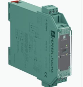

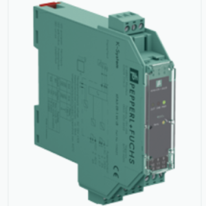
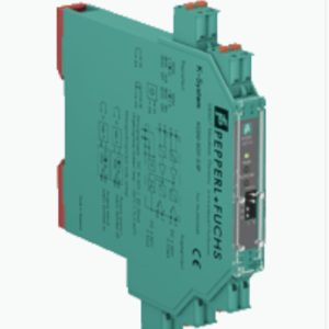
HART TRANSMITTER POWER SUPPLY, INPUT ISOLATOR FB3205B3 – PEPPERL FUCHS VIỆT NAM
Hãng: PEPPERL – FUCHS
Tên sản phẩm: HART TRANSMITTER POWER SUPPLY, INPUT ISOLATOR FB3205B3 – PEPPERL FUCHS VIỆT NAM
Bảo Hành : 12 Tháng ( chỉ bảo hành lỗi do nhà sản xuất )
Tình trạng hàng hóa mới 100%
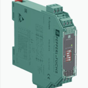
HART TRANSMITTER POWER SUPPLY, INPUT ISOLATOR FB3205B3
TÍNH NĂNG NỔI BẬT
Bộ nguồn máy phát cấp nguồn cho máy phát 2 và 3 dây.
Có thể kết nối các tín hiệu hoạt động từ thiết bị hiện trường được cấp nguồn riêng và máy phát 4 dây.
Lỗi đường dây hở và ngắn mạch được phát hiện.
- 4 kênh.
- Đầu vào Ex ia
- Lắp đặt trong các thùng phù hợp trong Vùng 1
- Mô-đun có thể được trao đổi dưới điện áp (trao đổi nóng)
- Nguồn cấp cho máy phát 2 dây 4 mA … 20 mA
- Mạch cung cấp 15 V (20 mA)
- Đầu vào từ tín hiệu hoạt động của máy phát 4 dây
- Giao tiếp HART thông qua bus trường hoặc bus dịch vụ
- Chế độ mô phỏng cho các hoạt động dịch vụ (buộc)
- Phát hiện lỗi đường dây (LFD)
- Tự giám sát vĩnh viễn
THÔNG SỐ KỸ THUẬT
| Slots | ||
|---|---|---|
| Occupied slots | 2 | |
| Supply | ||
| Connection | backplane bus | |
| Rated voltage | 12 V DC , only in connection with the power supplies FB92** | |
| Power dissipation | 1.5 W | |
| Power consumption | 2.7 W | |
| Internal bus | ||
| Connection | backplane bus | |
| Interface | manufacturer-specific bus to standard com unit | |
| Analog input | ||
| Number of channels | 4 | |
| Suitable field devices | ||
| Field device | pressure converter | |
| Field device [2] | flow converter | |
| Field device [3] | level converter | |
| Field device [4] | Temperature Converter | |
| Field device interface | ||
| Connection | 2-wire transmitter | |
| Connection [2] | 3-wire transmitter | |
| Connection [3] | 4-wire transmitter | |
| Connection | 2-wire transmitter (HART): Supply circuit: channel I 1+, 2-, channel II 5+, 6-, channel III 9+, 10-, channel IV 13+, 14- 3-wire transmitter: Supply circuit: channel I 1+, 4-, channel II 5+, 8-, channel III 9+, 12-, channel IV 13+, 16- Measurement loop: channel I 3+, 4-, channel II 7+, 8-, channel III 11+, 12-, channel IV 15+, 16- 4-wire transmitter (powered externally): Measurement loop: channel I 3+, 4-, channel II 7+, 8-, channel III 11+, 12-, channel IV 15+, 16- | |
| Transmitter supply voltage | min. 15 V at 20 mA ; 21.5 V at 4 mA | |
| Input resistance | 15 Ω | |
| Conversion time | max. 100 ms | |
| Line fault detection | can be switched on/off for each channel via configuration tool , configurable via configuration tool | |
| Short-circuit | factory setting: > 22 mA configurable between 0 … 26 mA | |
| Open-circuit | factory setting: < 1 mA configurable between 0 … 26 mA | |
| HART communication | yes | |
| HART secondary variable | no | |
| Transfer characteristics | ||
| Deviation | ||
| After calibration | 0.1 % of the signal range at 20 °C (68 °F) | |
| Influence of ambient temperature | 0.1 %/10 K of the signal range | |
| Resolution | 12 Bit (0 … 26 mA) | |
| Refresh time | 100 ms | |
| Indicators/settings | ||
| LED indication | Power LED (P) green: supply Diagnostic LED (I) red: module fault , red flashing: communication error , white: fixed parameter set (parameters from com unit are ignored) , white flashing: requests parameters from com unit Status LED (1-4) red: line fault (lead breakage or short circuit) |
|
| Coding | optional mechanical coding via front socket | |
| Directive conformity | ||
| Electromagnetic compatibility | ||
| Directive 2014/30/EU | EN 61326-1:2006 | |
| Conformity | ||
| Electromagnetic compatibility | NE 21:2007 | |
| Degree of protection | IEC 60529:2000 | |
| Environmental test | EN 60068-2-14:2009 | |
| Shock resistance | EN 60068-2-27:2009 | |
| Vibration resistance | EN 60068-2-6:2008 | |
| Damaging gas | EN 60068-2-42:2003 | |
| Relative humidity | EN 60068-2-78:2001 | |
| Ambient conditions | ||
| Ambient temperature | -40 … 60 °C (-40 … 140 °F) | |
| Storage temperature | -40 … 85 °C (-40 … 185 °F) | |
| Relative humidity | 95 % non-condensing | |
| Shock resistance | shock type I, shock duration 11 ms, shock amplitude 15 g, number of shocks 18 | |
| Vibration resistance | frequency range 10 … 150 Hz; transition frequency: 57.56 Hz, amplitude/acceleration ± 0.075 mm/1 g; 10 cycles frequency range 5 … 100 Hz; transition frequency: 13.2 Hz amplitude/acceleration ± 1 mm/0.7 g; 90 minutes at each resonance |
|
| Damaging gas | designed for operation in environmental conditions acc. to ISA-S71.04-1985, severity level G3 | |
| Mechanical specifications | ||
| Degree of protection | IP20 (module) , a separate housing is required acc. to the system description | |
| Connection | removable front connector with screw flange (accessory) wiring connection via spring terminals (0.14 … 1.5 mm2) or screw terminals (0.08 … 1.5 mm2) |
|
| Mass | approx. 955 g | |
| Dimensions | 57 x 107 x 132 mm (2.2 x 4.2 x 5.2 inch) | |
| Data for application in connection with hazardous areas | ||
| EU-type examination certificate | Presafe 19 ATEX 14056U | |
| Marking |  II 2(1)G Ex db eb q [ia Ga] IIC Gb II 2(1)G Ex db eb q [ia Ga] IIC GbII (1)D [Ex ia Da] IIIC I (M1) [Ex ia Ma] I |
|
| Supply | ||
| Voltage | 27 V | |
| Current | 90 mA | |
| Power | 588 mW (linear characteristic) | |
| Input | ||
| Voltage | 0.7 V | |
| Current | 2.78 mA | |
| Power | 2 mW (trapezoid characteristic curve) | |
| Internal capacitance | 242 nF | |
| Internal inductance | 0 mH | |
| Galvanic isolation | ||
| Input/power supply, internal bus | safe electrical isolation acc. to EN 60079-11, voltage peak value 375 V | |
| Directive conformity | ||
| Directive 2014/34/EU | EN 60079-0:2012+A11:2013 EN 60079-1:2014 EN 60079-5:2015 EN 60079-7:2015 EN 60079-11:2012 |
|
| International approvals | ||
| ATEX approval | Presafe 19 ATEX 14056U | |
| IECEx approval | IECEx PRE 19.0011U | |
| Approved for | Ex db eb q [ia Ga] IIC Gb [Ex ia Da] IIIC [Ex ia Ma] I |
|
| General information | ||
| System information | The module has to be mounted in appropriate backplanes and housings (FB92**) in Zone 1, 2, 21, 22 or outside hazardous areas (gas or dust). Here, observe the corresponding EC-type examination certificate. | |
Sản phẩm tương tự
Frequency Converters