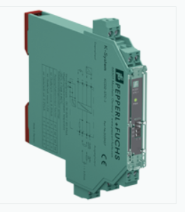
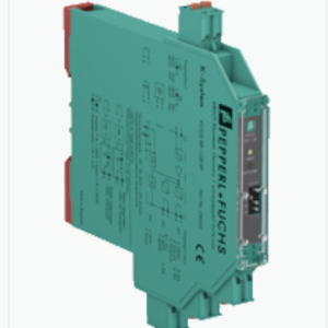
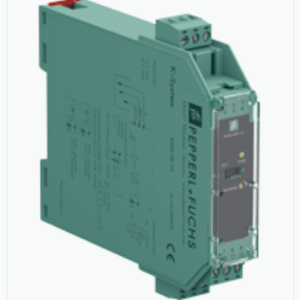
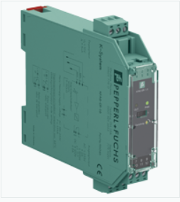
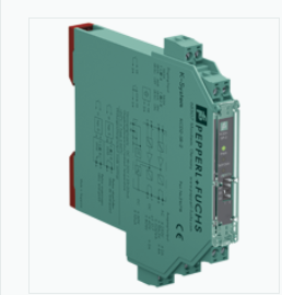
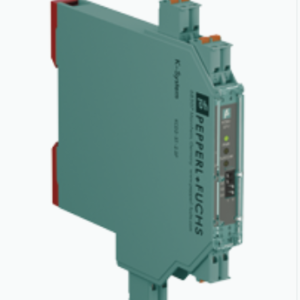
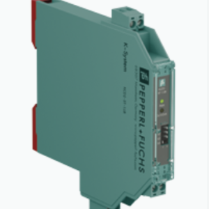
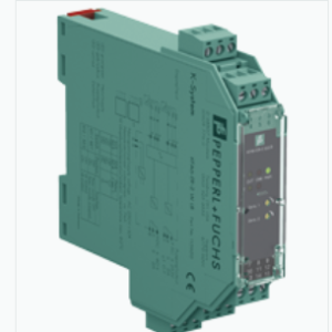
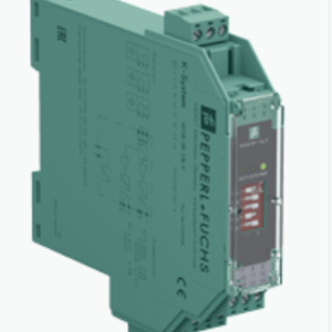
TRANSMITTER POWER SUPPLY KCD2-STC-1.2O – PEPPERL FUCHS VIỆT NAM
Bảo Hành : 12 Tháng ( chỉ bảo hành lỗi do nhà sản xuất )
Tình trạng hàng hóa mới 100%
SMART TRANSMITTER POWER SUPPLY KCD2-STC-1.2O
TÍNH NĂNG NỔI BẬT
Bộ điều hòa tín hiệu này cung cấp sự cách ly điện giữa các mạch trường và mạch điều khiển.
Thiết bị cung cấp bộ phát 2 dây, và cũng có thể được sử dụng với các nguồn hiện tại.
Thiết bị chuyển tín hiệu đầu vào tương tự sang phía điều khiển dưới dạng hai tín hiệu đầu ra cô lập.
Giao tiếp hai chiều được hỗ trợ cho các máy phát SMART sử dụng điều chế dòng điện để truyền dữ liệu và điều chế điện áp để nhận dữ liệu.
Đầu ra được chọn làm nguồn dòng, dòng chìm hoặc nguồn điện áp thông qua các công tắc.
Các ổ cắm kiểm tra kết nối của bộ giao tiếp HART được tích hợp vào các đầu cuối của thiết bị.
- Bộ điều hòa tín hiệu 1 kênh
- Nguồn cung cấp 24 V DC (Đường ray điện)
- Đầu vào cho máy phát SMART 2 dây và nguồn hiện tại
- Bộ chia tín hiệu (1 đầu vào và 2 đầu ra)
- Đầu ra kép 0/4 mA … 20 mA hoặc 0/1 V … 5 V
- Khối đầu cuối có ổ cắm thử nghiệm
- SIL 2 (SC 3) acc. to IEC/EN 61508
THÔNG SỐ KỸ THUẬT
| General specifications | ||
|---|---|---|
| Signal type | Analog input | |
| Functional safety related parameters | ||
| Safety Integrity Level (SIL) | SIL 2 | |
| Systematic capability (SC) | SC 3 | |
| Supply | ||
| Connection | Power Rail or terminals 9+, 10- | |
| Rated voltage | 19 … 30 V DC | |
| Ripple | within the supply tolerance | |
| Power dissipation | approx. 1.4 W at 20 mA transfer current, 250 Ω in both outputs | |
| Power consumption | 2 W | |
| Input | ||
| Connection side | field side | |
| Connection | terminals 1+, 2- (sink); 3+, 4- (source) | |
| Input signal | 0/4 … 20 mA | |
| Voltage drop | terminals 3, 4: ≤ 6.1 V at 20 mA | |
| Short-circuit current | terminals 1+, 2-: 25 mA | |
| Input resistance | terminals 1+, 2-: max. 500 Ω (BRAIN) (250 Ω load) |
|
| Available voltage | terminals 1+, 2-: ≥ 16 V at 20 mA , ≥ 18.5 V at 4 mA | |
| Output | ||
| Connection side | control side | |
| Connection | source: terminals 5-, 6+; 7-, 8+ sink: terminals 5+, 6-, 7+, 8- |
|
| Load | channel 1: 0 … 500 Ω (20 mA)/> 1 MΩ (5 V) channel 2: 0 … 500 Ω (20 mA)/> 1 MΩ (5 V) |
|
| Output signal | 0/4 … 20 mA or 0/1 … 5 V | |
| Ripple | max. 50 µA rms | |
| Transfer characteristics | ||
| Deviation | Iout < 20 µA (0.1 %); Vout < 7.5 mV (0.15 %) incl. calibration, linearity, hysteresis and fluctuation of supply voltage, at 20 °C (68 °F), 0/4 … 20 mA, 0/1 … 5 V | |
| Influence of ambient temperature | current output: 0.25 µA/K voltage output: 80 µV/K |
|
| Frequency range | field side into the control side: bandwidth with 0.5 Vpp signal 0 … 7.5 kHz (-3 dB) control side into the field side: bandwidth with 0.5 Vpp signal 0.3 … 7.5 kHz (-3 dB) |
|
| Settling time | 6 ms | |
| Rise time/fall time | 2 ms | |
| Galvanic isolation | ||
| Input/Output | basic insulation according to IEC 61010-1, rated insulation voltage 300 Veff | |
| Input/power supply | basic insulation according to IEC 61010-1, rated insulation voltage 300 Veff | |
| Output/power supply | functional insulation, rated insulation voltage 50 V AC | |
| Output/Output | functional insulation, rated insulation voltage 50 V AC | |
| Indicators/settings | ||
| Display elements | LED | |
| Control elements | DIP switch | |
| Configuration | via DIP switches | |
| Labeling | space for labeling at the front | |
| Directive conformity | ||
| Electromagnetic compatibility | ||
| Directive 2014/30/EU | EN 61326-1:2013 (industrial locations) | |
| Conformity | ||
| Electromagnetic compatibility | NE 21:2012 EN 61326-3-2:2008 |
|
| Degree of protection | IEC 60529:2001 | |
| Protection against electrical shock | UL 61010-1:2012 | |
| Ambient conditions | ||
| Ambient temperature | -20 … 60 °C (-4 … 140 °F) extended ambient temperature range up to 70 °C (158 °F), refer to manual for necessary mounting conditions |
|
| Mechanical specifications | ||
| Degree of protection | IP20 | |
| Connection | screw terminals | |
| Mass | approx. 100 g | |
| Dimensions | 12.5 x 124 x 114 mm (0.5 x 4.9 x 4.5 inch) (W x H x D) , housing type A2 | |
| Mounting | on 35 mm DIN mounting rail acc. to EN 60715:2001 | |
Sản phẩm tương tự
K-System
BỘ KHUẾCH ĐẠI TÍN HIỆU SWITCH AMPLIFIER, TIMER RELAY KFU8-SR-1.3L.V – PEPPERL FUCHS VIỆT NAM

