

UNIVERSAL INPUT/OUTPUT (HART) FB7304B3 – PEPPERL FUCHS VIỆT NAM
Hãng: PEPPERL – FUCHS
Tên sản phẩm: UNIVERSAL INPUT/OUTPUT (HART) FB7304B3 – PEPPERL FUCHS VIỆT NAM
Bảo Hành : 12 Tháng ( chỉ bảo hành lỗi do nhà sản xuất )
Tình trạng hàng hóa mới 100%
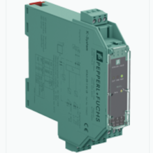
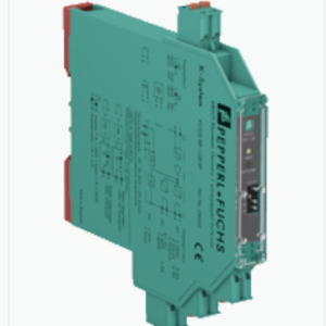
UNIVERSAL INPUT/OUTPUT (HART) FB7304B3
TÍNH NĂNG NỔI BẬT
Thiết bị là một mô-đun đa năng có thể định cấu hình. Mỗi kênh có thể hoạt động ở các chế độ sau:
– Là một đầu vào tương tự (AI), nó cấp nguồn cho các máy phát 2 dây.
– Là một đầu ra tương tự (AO), nó có thể điều khiển các van tỷ lệ, bộ chuyển đổi I / P hoặc các chỉ báo cục bộ.
– Là một đầu vào kỹ thuật số (DI), nó đọc các tiếp điểm khô.
– Là một đầu ra kỹ thuật số (DO), nó có thể điều khiển các bộ khuếch đại, bộ phát âm thanh hoặc đèn LED.
Có thể kết hợp I / O analog và kỹ thuật số.
Đèn LED kênh cho biết trạng thái của từng kênh. Đèn LED trắng cho biết AI, AO, DI, DO có được chọn hay không.
Các tín hiệu an toàn về bản chất được cách ly về mặt điện từ các bus và nguồn điện.
- 4 kênh
- Đầu vào với thiết bị đầu cuối Ex e plug-in
- Lắp đặt trong các thùng phù hợp trong Zone 1
- Mô-đun có thể được trao đổi dưới điện áp (trao đổi nóng)
- Đầu vào tương tự, đầu vào kỹ thuật số,
- đầu ra tương tự, đầu ra kỹ thuật số
- Mạch cung cấp 21,5 V (4 mA)
- Giao tiếp HART thông qua bus trường hoặc bus dịch vụ
- Chế độ mô phỏng cho các hoạt động dịch vụ (buộc)
- Phát hiện lỗi đường dây (LFD): một đèn LED trên mỗi kênh
- Tự giám sát vĩnh viễn
THÔNG SỐ KỸ THUẬT
| Slots | ||
|---|---|---|
| Occupied slots | 1 | |
| Supply | ||
| Connection | backplane bus | |
| Rated voltage | 12 V DC , only in connection with the power supplies FB92** | |
| Power dissipation | 2 W | |
| Power consumption | 3 W | |
| Internal bus | ||
| Connection | backplane bus | |
| Interface | manufacturer-specific bus to standard com unit | |
| Analog input | ||
| Number of channels | 4 | |
| Suitable field devices | ||
| Field device | pressure converter | |
| Field device [2] | flow converter | |
| Field device [3] | level converter | |
| Field device [4] | Temperature Converter | |
| Field device interface | ||
| Connection | 2-wire transmitter | |
| Connection | terminals 1+, 2-; 3+, 4-; 5+, 6-; 7+, 8- | |
| Transmitter supply voltage | min. 15 V at 20 mA ; 21.5 V at 4 mA | |
| Input resistance | 15 Ω | |
| Line fault detection | can be switched on/off for each channel via configuration tool , configurable via configuration tool | |
| Short-circuit | factory setting: > 21 mA Can be parameterized in the range 0 … 22 mA | |
| Open-circuit | factory setting: < 3.6 mA Can be parameterized in the range 0 … 22 mA | |
| HART communication | yes | |
| HART secondary variable | yes | |
| Analog output | ||
| Number of channels | 4 | |
| Suitable field devices | ||
| Field device | Proportional Valve | |
| Field device [2] | I/P converters | |
| Field device [3] | on-site display | |
| Connection | terminals 1+, 2-; 3+, 4-; 5+, 6-; 7+, 8- | |
| Current | 0 … 20 mA short-circuit protected | |
| Line fault detection | can be switched on/off for each channel via configuration tool , configurable via configuration tool | |
| Short-circuit | factory setting: < 50 Ω configurable between 0 … 26 mA | |
| Open-circuit | deviation of preset output value > 0.5 mA | |
| Load | max. 750 Ω at 20 mA | |
| HART communication | yes | |
| HART secondary variable | yes | |
| Watchdog | output off 0.5 s after serious fault | |
| Digital input | ||
| Number of channels | 4 | |
| Sensor interface | ||
| Connection [2] | volt-free contact | |
| Connection | terminals 1+, 2-; 3+, 4-; 5+, 6-; 7+, 8- | |
| Line fault detection | can be switched on/off for each channel via configuration tool | |
| Connection | mechanical switch with additional resistors (see connection diagram) | |
| Short-circuit | > 7 mA | |
| Open-circuit | < 0.1 mA | |
| Digital signals (active) | ||
| Switching point: ON | > 2.1 mA | |
| Switching point: OFF | < 1.2 mA | |
| Digital output | ||
| Number of channels | 4 | |
| Suitable field devices | ||
| Field device | Solenoid Valve | |
| Field device [2] | audible alarm | |
| Field device [3] | visual alarm | |
| Connection | terminals 1+, 2-, 3+, 4-, 5+, 6-, 7+, 8- | |
| Drive capability | 12 V / 22 mA | |
| Internal resistor | 385 Ω | |
| Current limit | 22 mA | |
| Open loop voltage | min. 22.7 V | |
| Line fault detection | can be switched on/off for each channel via configuration tool | |
| Test current | 0.4 mA | |
| Short-circuit | < 50 Ω | |
| Open-circuit | < 0.2 mA | |
| Transfer characteristics | ||
| Deviation | ||
| After calibration | 0.1 % of the signal range at 20 °C (68 °F) | |
| Influence of ambient temperature | 0.1 %/10 K of the signal range | |
| Resolution | 12 Bit (0 … 26 mA) | |
| Refresh time | approx. 100 ms (4 channels) | |
| Indicators/settings | ||
| LED indication | Power LED (P) green: supply Diagnostic LED (I) red: module fault , red flashing: communication error , white: fixed parameter set (parameters from com unit are ignored) , white flashing: requests parameters from com unit Status LED (1-4) red: line fault (lead breakage or short circuit) , yellow: state of digital I/O (0/1) Configuration LED (AI, AO, DI, DO) white: selected channel mode |
|
| Coding | optional mechanical coding via front socket | |
| Directive conformity | ||
| Electromagnetic compatibility | ||
| Directive 2014/30/EU | EN 61326-1:2013 | |
| Conformity | ||
| Electromagnetic compatibility | NE 21:2007 | |
| Degree of protection | IEC 60529 | |
| Environmental test | EN 60068-2-14 | |
| Shock resistance | EN 60068-2-27 | |
| Vibration resistance | EN 60068-2-6 | |
| Damaging gas | EN 60068-2-42 | |
| Relative humidity | EN 60068-2-78 | |
| Ambient conditions | ||
| Ambient temperature | -20 … 60 °C (-4 … 140 °F) | |
| Storage temperature | -25 … 85 °C (-13 … 185 °F) | |
| Relative humidity | 95 % non-condensing | |
| Shock resistance | shock type I, shock duration 11 ms, shock amplitude 15 g, number of shocks 18 | |
| Vibration resistance | frequency range 10 … 150 Hz; transition frequency: 57.56 Hz, amplitude/acceleration ± 0.075 mm/1 g; 10 cycles frequency range 5 … 100 Hz; transition frequency: 13.2 Hz amplitude/acceleration ± 1 mm/0.7 g; 90 minutes at each resonance |
|
| Damaging gas | designed for operation in environmental conditions acc. to ISA-S71.04-1985, severity level G3 | |
| Mechanical specifications | ||
| Degree of protection | IP20 (module) , a separate housing is required acc. to the system description | |
| Connection | removable front connector with screw flange (accessory) wiring connection via spring terminals (0.14 … 1.5 mm2) or screw terminals (0.08 … 1.5 mm2) |
|
| Mass | approx. 425 g | |
| Dimensions | 28 x 107 x 132 mm (1.1 x 4.2 x 5.2 inch) | |
| Data for application in connection with hazardous areas | ||
| EU-type examination certificate | FIDI 21 ATEX 0013 U | |
| Marking |  II 2G Ex db eb q IIC Gb II 2G Ex db eb q IIC Gb |
|
| Galvanic isolation | ||
| Input/power supply, internal bus | safe electrical isolation acc. to EN 60079-11, voltage peak value 375 V | |
| Directive conformity | ||
| Directive 2014/34/EU | EN 60079-0:2018 EN 60079-1:2014 EN 60079-5:2015 EN 60079-7:2015+A1:2018 |
|
| International approvals | ||
| ATEX approval | FIDI 21 ATEX 0013 U | |
| IECEx approval | ||
| IECEx certificate | IECEx FIDI 21.0003U | |
| IECEx marking | Ex db eb q IIC Gb | |
| General information | ||
| System information | The module has to be mounted in appropriate backplanes and housings (FB92**) in Zone 1, 2, 21, 22 or outside hazardous areas (gas or dust). Here, observe the corresponding EC-type examination certificate. | |